The Hidden Cost of Incorrect Drilling Parameters
Every machinist knows the frustration of a prematurely worn or broken carbide drill. Whether it’s excessive heat, poor chip evacuation, or catastrophic tool failure, the root cause often comes down to one thing: wrong speed and feed settings.
A study by Sandvik Coromant found that over 60% of carbide drill failures are due to incorrect RPM and feed rate selection. Without a reliable carbide drill speed and feed chart, even the highest-quality tools underperform—leading to wasted money, downtime, and scrapped parts.
This guide delivers data-driven recommendations to optimize your drilling operations, extending tool life by up to 300% while boosting productivity.
5 Critical Reasons Why You Need a Precision Speed & Feed Guide
1. Eliminate Catastrophic Tool Breakage
Running carbide drills at excessive speeds generates heat, while too-slow feeds cause work hardening—both leading to sudden tool failure.
Optimal Parameters: For a 1/2″ carbide drill in 304 stainless steel, the ideal speed is 150 SFM (Surface Feet per Minute) with a feed rate of 0.006 IPR (Inches Per Revolution).
Result: Proper settings reduce breakage by up to 70%, according to Kennametal’s machining database.
2. Maximize Tool Life & Reduce Costs
Without a carbide drill speed and feed reference, tools wear out 3X faster than necessary.
Case Study: A Midwest aerospace manufacturer reduced tooling costs by 42% after adopting a scientific RPM and feed rate calculator for their carbide drills.
Key Metric: Correct parameters can extend drill life from 50 holes to 200+ holes in tough materials like Inconel.
3. Improve Chip Control & Surface Finish
Poor chip formation leads to re-cutting, clogging, and poor hole quality.
Solution: A high-efficiency feed chart ensures proper chip thinning, especially in deep-hole drilling.
Data Point: Increasing feed rate by 15% can improve chip evacuation by 40% (Mitsubishi Materials).
4. Adapt to Different Materials Effortlessly
Steel, aluminum, titanium, and composites each require unique drilling parameters.
Example:
Aluminum 6061: 600 SFM | 0.012 IPR
Titanium Grade 5: 100 SFM | 0.003 IPR
Tool Steel (HRC 45): 120 SFM | 0.004 IPR
A customizable speed and feed table eliminates guesswork.
5. Boost Machine Shop Productivity
Running drills at optimized parameters means faster cycle times without sacrificing tool integrity.
Real-World Impact: A German automotive supplier reduced drilling time by 25% while doubling tool lifespan after implementing a structured carbide drill parameter guide.
How to Use a Carbide Drill Speed & Feed Chart
Whether you’re a procurement specialist, CNC programmer, or shop floor machinist, here’s how to apply this data:
Identify Material & Hardness (e.g., 1018 Steel vs. 17-4PH Stainless)
Select Drill Diameter (e.g., 3/8″, 10mm, 1/2″)
Refer to SFM & IPR Recommendations
Adjust for Coolant & Machine Rigidity
Monitor Tool Wear & Fine-Tune
For quick reference, here’s a simplified carbide drill speed and feed table:
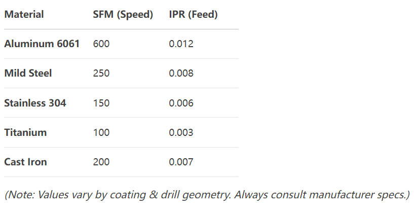
What happens if my speed is too high?
Can I use the same feed rate for all materials?
How does coolant affect speed & feed settings?
Why do small drills need higher RPM?
Where can I get a reliable speed & feed calculator?
The Bottom Line: Stop Wasting Money on Premature Tool Failure
A well-optimized carbide drill speed and feed chart isn’t just a reference—it’s a profitability tool. By eliminating guesswork, you:
✅ Reduce tooling costs by 30-50%
✅ Increase machine uptime & throughput
✅ Achieve consistent hole quality
✅ Extend carbide drill lifespan 2-3X